BACKGROUND
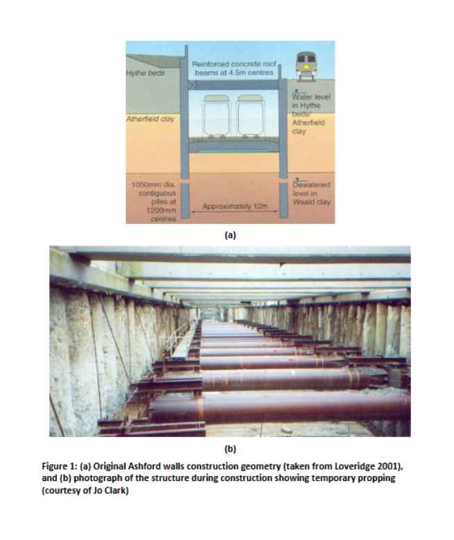
High Speed 1 (HS1) consists of 109 km of high-speed track and associated infrastructure linking the Channel Tunnel at Folkstone, Kent to the London terminus at St Pancras. Various measures were adopted to minimize the impact of HS1 in terms of noise and visual intrusion, particularly in urban areas. At Ashford, Kent, the railway runs through approximately 1.8 km of cut and cover tunnels and associated retained cuttings to minimize noise and to avoid crossing existing road and rail routes at grade. The sides of the cut-and-cover tunnels and propped retained cuttings were constructed using contiguous bored pile retaining walls, using piles varying in diameter from 900 mm to 1350 mm. Figure 1 shows a cross section through one of these walls.
It is proposed to extend the length of retained cutting, to provide additional lines running around Ashford station. At one location, a row of brick Victorian terrace houses runs parallel to the line of the cutting, with the nearest part of the houses just 10 m from the retaining wall. A contractor has proposed an outline scheme, including key aspects of the geometry required for the retained cutting (excavation depth, thickness of base slab). Figure 2 shows the dimensions, and soil conditions for, the new proposed excavation. You are asked to do some design calculations to establish the wall embedment depth, wall and prop structural loads, and wall and ground displacements.
Do You Need Assignment of This Question
CONSTRUCTION DETAILS
The geological succession in the Ashford area is summarised in Table 1, and geotechnical parameters and soil properties are given in Tables 2 and 3 and Figure 3.
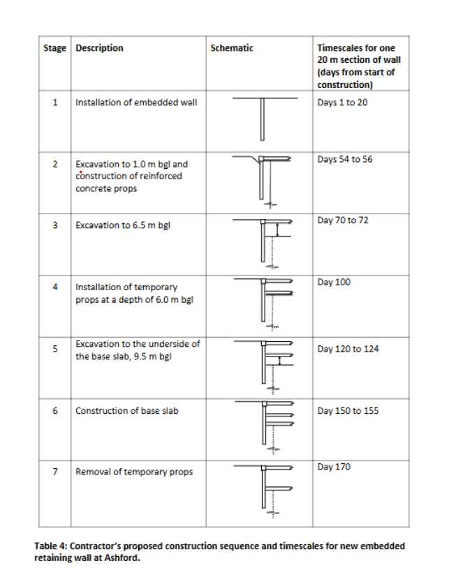
The contractor’s proposed construction sequence has seven stages, which are:
-
Install the diaphragm wall (you will need to determine the design embedment depth)
-
Excavate to a depth of 1.0 m bgl and install the upper, permanent props at 0.5 m bgl
-
Excavate to a depth of 6.5 m bgl
-
Install the temporary props at a depth of 6.0 m bgl
-
Excavate to a depth of 9.5 m bgl
-
Construct the base slab of 1.0 m depth
-
Remove the temporary props
This construction sequence is shown schematically in Table 4.
Due to the plant available, the contractor would prefer to build a 1300 mm thick concrete diaphragm panel wall. It is intended that the top props will be of reinforced concrete of cross section 1000 mm by 1000 mm and spaced at 4.5 m centres, and that the temporary props will be of tubular steel sections of 1000 mm diameter and wall thickness 25 mm. The base slab is a 1.0 m thick reinforced concrete section.
.")
| Stratum | Description |
|---|---|
| Gault Clay | Very stiff fissured clay |
| Folkstone Beds | Very dense sand |
| Sandgate Beds | Silty sand and silty clay |
| Hythe Beds | Orange brown silty or clayey fine sand with one or two poorly developed layers of sandstone (more usually interbedded Limestone (Rag) and very dense sand or weak sandstone (Hassock)) |
| Atherfield Clay | Stiff to very stiff plastic clay, frequently closely fissured. Zones containing thin silt partings were present at some locations, occurring more frequently with depth |
| Weald Clay | Stiff to very stiff clay with numerous fissures, silt partings and laminations and bands of siltstone typically 100 – 200 mm thick |
Table 1: General geological succession in the central Ashford area (from Richards et al, 2006)
")
| Stratum | Unit weight (Mg/m³) | Friction angle, φ′ | Estimated OCR | Estimated K₀ = (1 – sinφ′) × OCRⁿⁱⁿᵛ | Hydraulic conductivity (permeability), k (m/s) |
|---|---|---|---|---|---|
| Hythe Beds | 2.0 | 35° | 7.3 to 9.3 | 1.35 to 1.5 | 2 × 10⁻⁴ |
| Atherfield Clay | 2.05 | 25° | 3.5 to 10.3 | 1.0 to 1.5 | 2 × 10⁻⁹ |
| Weald Clay | 2.05 | 25° | 4.5 to 10.7 | 1.1 to 1.5 | 2 × 10⁻⁶ |
Table 2: Soil characterisation and design parameters and estimated in situ earth pressure coefficients (adapted from Loveridge, 2001 and Richards et al., 2006)
| Stratum | Young’s modulus at top surface of stratum (kPa) | Gradient increase of Young’s modulus with depth (kPa/m) |
|---|---|---|
| Hythe Beds | 1800 | 4860 |
| Atherfield Clay | 3600 | 3640 |
| Weald Clay | 18200 | 3200 |
Table 3: Soil stiffnesses (Young’s moduli) based on values given by Loveridge (2001).
Buy Answer of This Assessment & Raise Your Grades
YOUR TASK
PART 1:
Carry out Ultimate Limit State (ULS) limit equilibrium design calculations to determine the design depths of embedment and prop loads at the end of Stage 7. Follow the guidelines given in the CIRIA report C760 (Gaba et al., 2017), for Eurocode design approach DA1C2 which are [also see CIRIA guide page 190]:
i. Apply a factor of safety of 1.25 to tanφ′, i.e. tanφ′design = (tan φ′)/1.25;
ii. Take wall friction angle δ = 1.0 × φ′;
iii. Assume that a variable unfavourable surcharge of 10 kPa applies to the ground surface at the top of the wall, and that this is increased by a partial factor of 1.3;
iv. Allow for an overdig of 10% of the excavation depth H up to a maximum of 0.5 m, where H is taken as the height retained below the lowest support level for a propped wall.
Assume fully active pressures in the soil behind the wall and fully passive pressures in front, with the design (factored) value of φ′ in each case. Make suitable assumptions regarding the pore water pressures, on the basis of the information on the in situ groundwater regime given in Figure 3 and the permeabilities in Table 2, and potential steady state flow conditions around the wall. You only need to carry out drained effective stress calculations: the quite high bulk permeability of the Weald Clay is likely to limit undrained behaviour of the clay.
PART 2:
Carry out a soil-structure interaction ULS analysis (with the factored soil strength) using the pseudo-finite element program FREW (see separate notes starting on page 11), to determine the required depth of embedment and the ULS bending moments and prop loads for all construction stages. To arrive at the correct earth pressures for Stage 7 at the end of the analysis, you will need to model all the construction stages in FREW. Additional parameters you will need to run this analysis are given in Table 5.
Carry out a Serviceability Limit State (SLS) analysis of the wall with the design depth of embedment (i.e. that from the ULS) and the unfactored soil strength, to calculate the SLS bending moments, prop loads and wall displacements, again modelling all construction stages. The provision for an unplanned overdig does not apply in the SLS.
PART 3:
Using the charts of past case history data given in CIRIA C760, estimate the vertical ground settlements that would occur behind the wall for Stage 7, both adjacent to the structure and 10 m away from it. You should use Figures 6.9 and 6.5, which are on pages 161 and 168 of C760.
| Pre-excavation lateral earth pressure coefficient K | see Table 2 |
|---|---|
| Young’s modulus of soil E | see Table 3 |
| Poisson’s ratio for soil ν | 0.3 |
| Wall flexural rigidity (bending stiffness) EI | see Page 2 for wall thickness and plan geometry, and take E₀ for concrete as 31 × 10⁶ kN/m². Follow the guidance in C760 (see page 85) on changes to E during construction and in long-term wall service. |
| Prop stiffness k | see Page 2 for concrete and steel prop geometry, and take E₀ for concrete as 31 × 10⁶ kN/m². Eₚ for the props should be similarly reduced to account for creep and relaxation of the concrete (i.e., you should again follow the advice on page 85 of C760). |
| Width of excavation | see Figure 2 |
Table 5. Additional parameters required for FREW analyses.
WRITE-UP
Your write-up should comprise the following sections:
i. Detail the input parameters (factored strengths, soil/wall friction angles, earth pressure coefficients, pore water pressure conditions, design wall geometry allowing for overdig etc.) for the limit equilibrium ULS calculation, for the stage analysed (Stage 7). [12 marks]
ii. Provide your design wall embedment depth calculation set out as per Example 9.1, pp. 483–491, SMCA 3rd Edition [or Example 10.1 on pp. 557–563 of SMCA 2nd Edition], with soil stresses and pore water pressures at key depths set out in tabular form, clearly defined stress blocks, calculation of resulting forces and lever arms, and force/moment equilibrium calculations, for Stage 7. Detail the calculation of the prop loads for the design depth of embedment. [18 marks]
iii. Detail and justify the input assumptions and parameters for your FREW analyses, including the design wall geometries, water pressures, soil strength and stiffness, and the prop and wall stiffnesses used. [12 marks]
iv. Show graphical output from the FREW soil-structure interaction analyses for Stage 7 (one image in each case to show effective earth and water pressures, a second to show the bending moment, shear force and prop load, and a third to show wall displacements), for both ULS and SLS conditions at both stages. [18 marks]
v. Show your calculations for the vertical settlements of the ground behind the wall determined described in Part 3 above (for Stage 7). Please clearly state the vertical settlements adjacent to and 10 m behind the wall. [5 marks]
vi. Draw up a table to compare the results from the limit equilibrium calculations and FREW analyses, giving maximum wall bending moment (FREW only), prop loads, wall embedment depth, and maximum horizontal wall displacement and vertical ground settlement (FREW only) for each of the analyses at Stage 7. [5 marks]
vii. For Stage 7, provide a brief commentary on the reasons for the differences between LE ULS and FREW ULS results, and FREW ULS and FREW SLS results. [12 marks]
viii. State which calculation results (from any stages of the analyses) you would use as the structural design loads for the wall and props, and explain why. [6 marks]
ix. Comment on the magnitude and likely accuracy of the horizontal (wall) movements and vertical (ground) settlements obtained by calculation approaches in Part 2 and Part 3. Would any further action be required to protect the terraced houses 10 m behind the wall during construction? [6 marks]
x. Explain how you might achieve a more efficient wall design. [6 marks]
NOTES ON ASSIGNMENT PREPARATION
-
Your assumptions and calculations must be clearly set out so as to facilitate checking. You will lose marks if you do not comply with this requirement.
-
Please keep your assignments concise: it should be possible to detail the calculations and explain assumptions on fewer than 15 sides. There are no marks available for repeating the question, or explaining basic soil mechanics concepts (e.g. effective stress) – so you do not need to do that.
-
Neat handwritten calculations are fine – you do not have to use Word.
Are You Looking for Answer of This Assignment or Essay
The post Geotechnical Engineering Assignment 2025/26 – University Of Surrey (UniS) appeared first on Students Assignment Help UK.